X-ray computed tomography (CT) is a measuring technique which has become an important technology in the production environment over the last years. Due to a number of advantages of CT compared to, e.g., coordinate measuring machines (CMMs), CT has been recently spread in the field of manufacturing metrology and coordinate metrology and is currently becoming a more and more important measuring technique for dimensional measurements. This is mainly due to the fact that, with CT, a complete three-dimensional model of the scanned part is in a relatively short time visualized using a computer, and measurements of outer as well as inner geometries can be performed with micrometer resolution. A flow chart of a typical dimensional CT measurement process is shown in Figure 1.
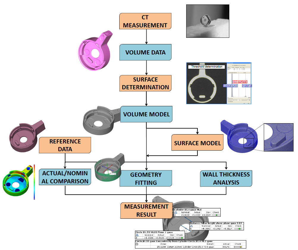
Figure 1: Flow chart of a typical dimensional CT measurement process [Müller].
The result of dimensional CT measurements, as of every other measuring instrument, has to be accompanied with a statement about the measurement uncertainty. The knowledge about measurement uncertainty is an important factor for decision making about manufactured parts. However, due to many influences in CT, estimation of the uncertainty is a challenge, also because standardized procedures and guidelines are not yet available.
In this WP, several methods for uncertainty estimation were applied in connection with a number of industrial components as well as calibrated workpieces. Measurement uncertainty was often used as a parameter for quantification of a selected influence quantity. Uncertainty estimation using the substitution method appeared to be well applicable to CT measurements in production environment. By performing repeated measurements of the calibrated workpiece, characterization of a CT system under study for a specific task part was achieved. The task-specific measurement uncertainty from repeated measurements was then transferred to other uncalibrated workpieces. It was documented that CT is a well-established technique for tolerance verification of manufactured parts.
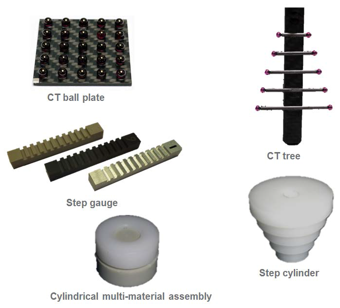
Figure 2: Five reference objects for performance characterization of industrial CT systems developed at DTU [
Angel,
Müller].
Five reference objects for performance characterization of industrial CT systems were developed within the scope of this WP. Namely, CT ball plate, CT tree, step gauge, step cylinder, and a cylindrical multi-material assembly (see Figure 10), which were further used for identification, characterization and correction of measurement errors in the CT volume. Their application appeared to be suitable for this task. Because the five objects consist of ruby spheres, carbon fibre and polymers, CT scans do not produce image artifacts, and evaluation of distances is robust. The role of material and form errors present in industrial parts was investigated in another work package (WP5).
Several methods for scale error correction were implemented to correct original reconstructed volume data sets. E.g. this was done using the CT ball plate, the CT tree, the calibrated features measured by CMM and the ”data base” approach considering a previous characterization of the CT system with a number of CT measurements using a calibrated ball bar. As, for example, methods using the two reference objects consisting of spheres, is a classical way for correction of the voxel size, by comparing the distance between centres of spheres measured by CT to calibrated values, the application of calibrated features was documented on a metallic as well as on a plastic part and resulted in comparable observations. The method using the ”data base” approach seemed to work well, but its applicability shall be further validated.
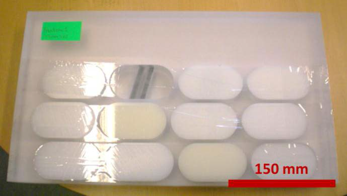
Figure 3: Synthetic volume phantom for performance characterization of clinical CT systems developed at DMRI [Angel].
Seven synthetic volume phantoms were developed by DMRI for the meat industry, to be used instead of real pig carcasses. A volume phantom consists of several polymer components, such as polymethylmethacrylate (PMMA), polyethylene (PE) and polyvinylchloride (PVC), see Figure 3. The volume phantoms were further used for identification, characterization and correction of volume measurement errors in a clinical CT. Because the volume phantoms consist of polymers, CT scans does not produce image artifacts, and evaluation of volumes is robust. Calibrations were performed using the pycnometer method, based on water displacement, to determine the reference volume of all materials in the set of volume phantoms before assembly. The phantoms were used for performance characterization of clinical CT systems under another work package (WP5). Their further application in WP5 appeared to be suitable.
A half carcass phantom (Figure 4) was developed for fat determination of meat end products. The scope of this phantom is for identification, characterization and correction of geometrical measurement errors in a clinical CT. The phantom includes several free form surfaces creating a challenge to the calibration system and methodology. Such details have to be included to represent vital dimensions of the real carcass, dimensions that must be determined using automated software algorithms.
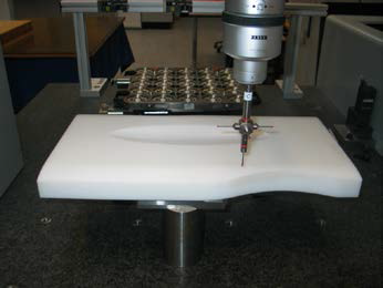
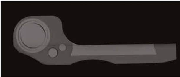
Figure 4: Half carcass phantom for performance characterization of clinical CT systems developed at DMRI and calibrated at DTU Mekanik (up), and thereafter scanned in a CT (down) [PC13].